
COMING SOON
|
|
But Wait..There's More!
Fluid Ear Medication Dispenser System
Patent #US10736783
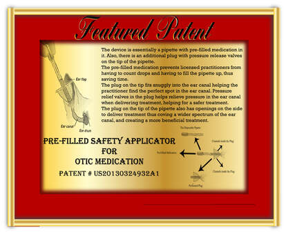
Patent description: A dispensing assembly has a forward positioning section, an intermediate storage section, and a rearward operational section. The forward positioning section has an exterior end in a semi-spherical configuration with a forward passageway. The intermediate storage section has a storage chamber for fluid medication whereby the fluid medication may be fed through the forward passageway and out of the exterior end of the forward positioning section. A door in the intermediate storage section facilitates the addition of fluid medication. A piston is in the intermediate storage section. The rearward operational section drives the piston axially within the storage chamber whereby fluid medication in the storage chamber may be fed through the forward passageway and out of the exterior end of the positioning section into the ear of the pet.
Patent #US10736783
Patent description: A dispensing assembly has a forward positioning section, an intermediate storage section, and a rearward operational section. The forward positioning section has an exterior end in a semi-spherical configuration with a forward passageway. The intermediate storage section has a storage chamber for fluid medication whereby the fluid medication may be fed through the forward passageway and out of the exterior end of the forward positioning section. A door in the intermediate storage section facilitates the addition of fluid medication. A piston is in the intermediate storage section. The rearward operational section drives the piston axially within the storage chamber whereby fluid medication in the storage chamber may be fed through the forward passageway and out of the exterior end of the positioning section into the ear of the pet.
Bed Bug Detector System
Patent #US10736309
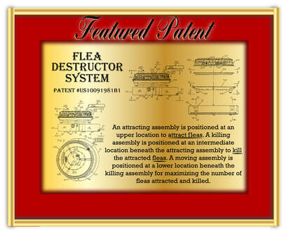
Patent description: A bed bug attracting assembly is positioned at an upper location. A bed bug killing assembly is positioned at an intermediate location beneath the attracting assembly. A base assembly is positioned at a lower location beneath the killing assembly for maximizing the number of bed bugs attracted and killed. A control assembly has a user visible digital UPC code, a battery power percentage indicator with an ON/OFF button and a sound activated switch, a cell phone with a macro-lens, and two light emitting diode positioned adjacent thereto to illuminate bed bugs. An electric grid triggers a camera detector. A CO2 self-emitting device includes graphite and an electrical charge. A platform with pores holds a lure over a miniature fan. A programmable computer is preprogrammed to modulate attraction modalities. A GPS transmitter is activated to sent to receives to secure the area of infestation.
Patent #US10736309
Patent description: A bed bug attracting assembly is positioned at an upper location. A bed bug killing assembly is positioned at an intermediate location beneath the attracting assembly. A base assembly is positioned at a lower location beneath the killing assembly for maximizing the number of bed bugs attracted and killed. A control assembly has a user visible digital UPC code, a battery power percentage indicator with an ON/OFF button and a sound activated switch, a cell phone with a macro-lens, and two light emitting diode positioned adjacent thereto to illuminate bed bugs. An electric grid triggers a camera detector. A CO2 self-emitting device includes graphite and an electrical charge. A platform with pores holds a lure over a miniature fan. A programmable computer is preprogrammed to modulate attraction modalities. A GPS transmitter is activated to sent to receives to secure the area of infestation.
Sleep Security Method
Patent #US10729374
Patent Description: A sleep security method comprises the steps of providing a bed; providing at least one sensor for the detecting of a sleeping condition and for generating a signal in response to such detecting, the at least one sensor being located in operative proximity to the bed; providing a printer; providing a transceiver; operatively coupling the at least one sensor to the printer through the transceiver; and creating a written record by the printer of the detecting of the sleeping condition.
Detection of COVID-19
Patent #US20200214649
Patent Description: The steps of the method are: providing a generator adapted to produce specific wavelengths to maximize light emissions; providing a scintillator in operative proximity to the generator, the scintillator having an associated scintillator screen of a specific phosphor or other excitive type sensitive to various wavelengths, the scintillator being sensitive to a wavelength that maximizes light emissions; positioning a patient to be diagnosed between the generator and the scintillator; emitting a specific wavelength from the generator to and through the patient onto the scintillator screen whereby the associated scintillator screen will light up and sparkle to produce a light image of the patient; providing a camera in operative proximity to the scintillator screen to record the light image produced on the scintillator screen; providing a computer with a computer screen and software; capturing and analyzing the recorded light images from the camera; and obtaining a diagnosis for treatment of the patient.
Cat Thumper System
Patent #US10517272B1
Patent Description: A housing has a top, a bottom, and a side wall. A spacer is coupled to and depends downwardly from the bottom of the housing creating a chamber beneath the bottom of the housing within the spacer. A rod is has an upper end within the housing and a lower end there beneath. Drive mechanisms located within the housing and coupled to the rod reciprocate the rod between a retracted position and an extended position. The retracted position is with the lower end within the chamber. The extended position being with the lower end extending beneath the chamber.
Animal Clinical Carrier System
Patent #US10492462
Patent Description: An animal carrier has a top, bottom, front, back and sides forming a chamber, and a door. Fixed slots are formed in the sides with shiftable panels overlying the sides. The panels have shiftable slots with shiftable blockers between the slots. an enlarged opening in the front has horizontal edges extending from the top and bottom and vertical edges extending from the sides. A vertically disposed shiftable plate within the chamber is adapted to advance to expel the animal patient from the chamber. Wheels and associated fans function to create an airflow to minimize a force to move the system along a floor. A drainboard is positioned within the chamber on the bottom for draining urine to a collection zone. A slot above the collection zone is for removable receipt of a test slip for clinical analysis of the urine.
Ointment Application System
Patent #US10492992
Patent Description: An ointment squeeze ball has an exit orifice for dispensing ointment. A colorant squeeze ball has an exit orifice for dispensing colorant. A mixing tube has an input end, an exit applicator tip, and an elongated passageway with helical mixing vanes. A central component in a Y-shaped configuration with a central passageway removably couples the ointment squeeze ball and the mixing tube. The central component has a lateral leg with a lateral passageway removably coupling the colorant squeeze ball and an intermediate region of the central passageway.
Mobile Insect Killing System
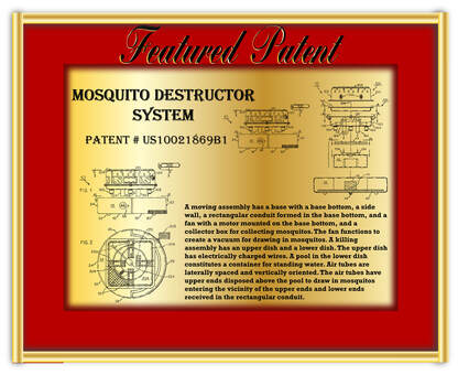
Patent #US10021871
Patent Description: A base assembly has an upward plate, a downward plate, a side wall, a front, a back, and laterally spaced sides. A drive assembly has drive wheels which extend downwardly from the downward plate and has a caster wheel. The drive assembly also has proximity sensors. A vacuum assembly has a vacuum slit formed in the downward plate between the laterally spaced sides. A source of vacuum pulls a vacuum through the vacuum slit. A tower assembly attracts and kills insects while the base assembly and tower assembly are driven by the drive assembly and the vacuum assembly vacuums up insects.
System of Adaptable Modular Utility Devices
Patent #US9510985B2
Patent Description:
A foot support is disposed in a horizontal plane and is positioned on a housing of the lower section of a motorized wheel chair rearwardly of upwardly facing receptors. A control post has a lower end removably received in the receptors and an upper end having an upper cross piece with spaced hand grips. A control assembly is coupled to the upper cross piece. A motor within the housing powers laterally spaced drive wheels. A steerer within the housing directs directional wheels. The control assembly includes a drive wheel controller for varying the speed of the system and a directional wheel controller for varying the direction of the system.
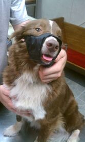
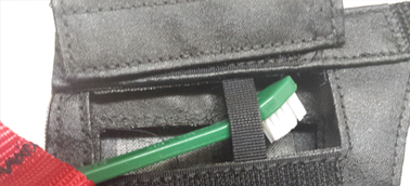
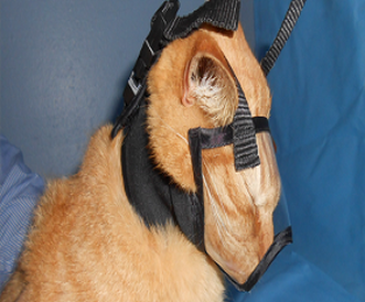
Dog Tooth Brushing System
Patent #US9021992
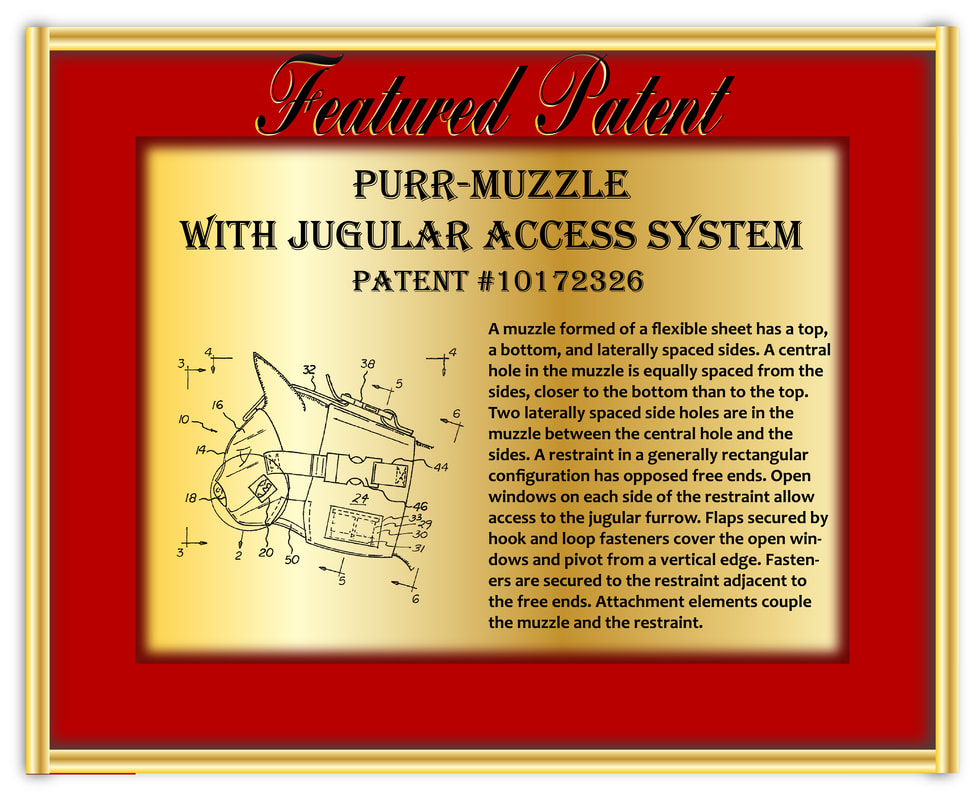
Patent Description: A windowed muzzle has left and right side sections, a lower section, an upper section and a rear section. A left window is in the left side section and a similarly configured right window is in the right side section. A left flap is configured and sized to cover the left window and a similarly configured right flap is configured and sided to cover the right window. A securement assembly selectively retains each flap in a raised orientation above the window or in a lowered orientation covering the window. A brushing assembly has a flexible strap coupled to the lower section. The brushing assembly includes a toothbrush removably coupled to the flexible strap.
Patent #US9021992
Patent Description: A windowed muzzle has left and right side sections, a lower section, an upper section and a rear section. A left window is in the left side section and a similarly configured right window is in the right side section. A left flap is configured and sized to cover the left window and a similarly configured right flap is configured and sided to cover the right window. A securement assembly selectively retains each flap in a raised orientation above the window or in a lowered orientation covering the window. A brushing assembly has a flexible strap coupled to the lower section. The brushing assembly includes a toothbrush removably coupled to the flexible strap.
Audio and Light Fungal Growth Indicator
Patent #US20140085085
Patent Description: A device was invented with a sensor that would allow for determining fungal growth. When fungal growth occurs the sensors would be activated emitting audio, light and actual voice commands. The device provides; a low cost, simplicity of use and function, and its ability to fulfill a need for the means to determine growth of fungi placed behind closed doors or beyond the point of view. This device may be used for pathogenic fungal growth in medical and veterinary facilities, also in laboratories examining environmental pollution. The automatic sensing methodology also allows for a reduced chance for the preparer to be contaminated through exposure by reducing the need of continual examination of the fungal growth.
Flea Trap with Advanced Attractant and Multiple Flea Killing Methods
Patent #US20140020279
Patent Description: The device is a flea trap device with multiple methods of killing and trapping the unwanted fleas. The device utilizes a fake animal which moves via small vibrators under the fur, and is warm much like a real one. The feline's eyes light up. This device utilizes heat, motion, and light to attract the fleas much like a real one. Also every so many minutes it. sprays carbon dioxide on itself which is what is used to kill the fleas. The animal has sticky tape around it which prevents the fleas from escaping or moving. Around the fake animal is a cage which prevents animals, and young ones from entering the trap. This flea trap is the first one to utilize all methods of attracting fleas from a 360 degree angle.